How does a ammeter work?
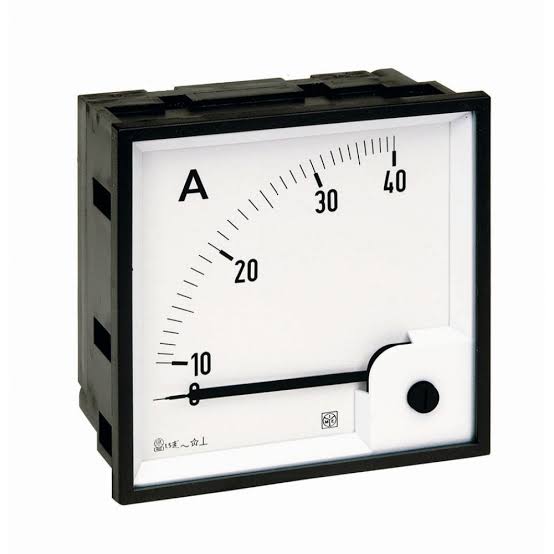
An ammeter (from Ampere Meter) is a measuring instrument used to measure the current in a circuit. Electric currents are measured in amperes (A), hence the name. Instruments used to measure smaller currents, in the milliampere or microampere range,
Working Principle of Ammeter
The main principle of ammeter is that it must have a very low resistance and also inductive reactance. Now, why do we need this? Can’t we connect an ammeter in parallel? The answer to this question is that it has very low impedance because it must have very low amount of voltage drop across it and must be connected in series connection because current is same in the series circuit.Also due to very low impedance the power loss will be low and if it is connected in parallel it becomes almost a short circuited path and all the current will flow through ammeter as a result of high current the instrument may burn. So due to this reason it must be connected in series.
Types of Ammeter
There are many types of ammeter
1.Moving coil
2.Moving magnet
3.Electrodynamic
4.Moving iron
5.Digital
1.Moving coil
There are two spiral springs to provide the restoring force. The uniform air gap between the iron core and the permanent magnet poles make the deflection of the meter linearly proportional to current. These meters have linear scales. Basic meter movements can have full-scale deflection for currents from about 25 microamperes to 10 milliamperes.
Because the magnetic field is polarised, the meter needle acts in opposite directions for each direction of current. A DC ammeter is thus sensitive to which way round it is connected; most are marked with a positive terminal, but some have centre-zero mechanisms and can display currents in either direction. A moving coil meter indicates the average (mean) of a varying current through it, which is zero for AC. For this reason moving-coil meters are only usable directly for DC, not AC.This type of meter movement is extremely common for both ammeters and other meters derived from them, such as voltmeters and ohmmeters. Although their use has become less common in recent decades, this type of basic movement was once the standard indicator mechanism for any analogue displays involving electrical machinery.
Moving Coil Instruments are used for measuring DC quantities. They can be used on AC systems when fed through bridge rectifiers, but some products are rectified moving coil and can be used in ac systems directly.
2.Moving magnet
Moving magnet ammeters operate on essentially the same principle as moving coil, except that the coil is mounted in the meter case, and a permanent magnet moves the needle. Moving magnet Ammeters are able to carry larger currents than moving coil instruments, often several tens of Amperes, because the coil can be made of thicker wire and the current does not have to be carried by the hairsprings. Indeed, some Ammeters of this type do not have hairsprings at all, instead using a fixed permanent magnet to provide the restoring force
3.Electrodynamic
An electrodynamic movement uses an electromagnet instead of the permanent magnet of the d'Arsonval movement. This instrument can respond to both alternating and direct current and also indicates true RMS for AC.
4.Moving iron
Moving iron ammeters use a piece of iron which moves when acted upon by the electromagnetic force of a fixed coil of wire. This type of meter responds to both direct and alternating currents (as opposed to the moving-coil ammeter, which works on direct current only). The iron element consists of a moving vane attached to a pointer, and a fixed vane, surrounded by a coil. As alternating or direct current flows through the coil and induces a magnetic field in both vanes, the vanes repel each other and the moving vane deflects against the restoring force provided by fine helical springs.The deflection of a moving iron meter is proportional to the square of the current. Consequently, such meters would normally have a non linear scale, but the iron parts are usually modified in shape to make the scale fairly linear over most of its range. Moving iron instruments indicate the RMS value of any AC waveform applied.
5.Digital
Digital ammeter designs use a shunt resistor to produce a calibrated voltage proportional to the current flowing. This voltage is then measured by a digital voltmeter, through use of an analog to digital converter (ADC); the digital display is calibrated to display the current through the shunt. Such instruments are generally calibrated to indicate the RMS value for a sine wave only but some designs will indicate true RMS (sometimes with limitations as to wave shape).
Application
The majority of ammeters are either connected in series with the circuit carrying the current to be measured (for small fractional amperes), or have their shunt resistors connected similarly in series. In either case, the current passes through the meter or (mostly) through its shunt. Ammeters must not be connected directly across a voltage source since their internal resistance is very low and excess current would flow. Ammeters are designed for a low voltage drop across their terminals, much less than one volt; the extra circuit losses produced by the ammeter are called its "burden" on the measured circuit.
Ordinary Weston-type meter movements can measure only milliamperes at most, because the springs and practical coils can carry only limited currents. To measure larger currents, a resistor called a shunt is placed in parallel with the meter. The resistances of shunts is in the integer to fractional milliohm range. Nearly all of the current flows through the shunt, and only a small fraction flows through the meter. This allows the meter to measure large currents. Traditionally, the meter used with a shunt has a full-scale deflection (FSD) of 50 mV, so shunts are typically designed to produce a voltage drop of 50 mV when carrying their full rated current.







0 Comments